
(a) area
(b) area distribution
(c) aspect ratio
(d) shape
(e) airfoil
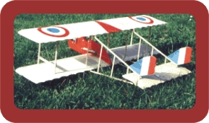
There's no plausible reason to use a wing area very different from a comparable monoplane stunter. We should keep what we're used to and have found adequate. Usually that means a wing loading of about 13oz/sq.inch. You would think that two wings ought to be heavier than a single wing of the same area - and remember those wing struts. But in my experience “ it ain’t necessarily so”. In fact each of the two wings can be built lighter because we have the struts to restore rigidity.More on that later. Personally I'd prefer to use a little less area than a monoplane with weight and drag reduction in mind. But that’s purely my own view, and I don’t expect anybody to follow my thoughts. Most full-size biplanes feature a larger top wing. Maybe this serves quite well for their intended use. However, for our requirements a layout as symmetrical as possible is logical. So I’d suggest equal-span wings of identical area and shape.
One cannot talk about drag reduction without mentioning aspect ratio. Aspect ratio ( AR ) is the relation of chord to wing span. The smaller the chord (for a given area) the smaller the induced drag. There’s less induced drag on high AR wings. A lot of drag is produced by the wing tips ( vortexes ). And our biplane has four of them. Trying to reduce this drag calls for high AR wings. 'Normal' stunters have an aspect of about 5:1. For a biplane maybe we should consider a higher figure. Depending on airplane size I’d like to get closer to 6:1 . We must remember rigidity, too! For reasons of simplicity a constant-chord wing can be used - it really doesn't look ugly on a biplane, really. For yawing stability we use the usual wing sweep of around three degrees. Again, for symmetry I'd prefer exactly the same shape for both wings.
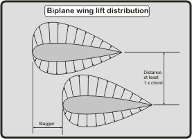
The wings should be located at an equal distance from the engine thrustline to give identical flying characteristics during inside and outside maneouvres. The distance between wings should be no less than one chord width; preferably a little more. The airflow around the wing (while producing lift ) will be influenced even at a considerable distance from the wing surface. If both wings are too close to each other the airflow from one wing interferes with the other, thus reducing lift and probably increasing drag. The bulk of pressure occurs at the front one-third of the airfoil. So if we use stagger (the horizontal difference in wing position) we effectively separate the wings even more and avoid airflow interference.
I see no reason for changing any other dimensions. We can use the same fuselage moment arms, CG location, and tailplane size (which is somewhere between 20 and 25% of wing area; the smaller amount for the non-flapped configuration, because we don't have the dampening effect of the flaps). Many builders are inspired by the beautiful lines of the Pitt’s Special and it’s stubby fuselage. However for our purpose these dimensions are not exactly what we need. From my experience I’d rather recommend those well known traditional proportions we’ve come to use on our monoplane airplanes. For those anxious aesthetes: that beautiful look doesn’t suffer at all!
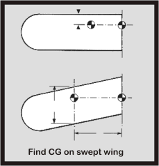
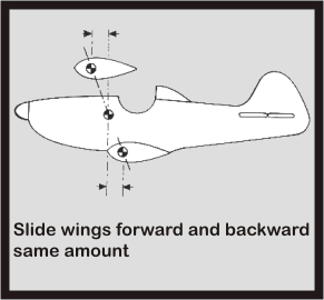
CG location on biplanes causes some enthusiasts to shudder but it's not really a problem. Rather than drawing some fancy plans and desperately guessing or calculating the CG position, I use the opposite procedure. It’s not very scientific and the experts will have their hairs stand on end. But it’s practical and easy and doesn’t require a doctor in mathematics. Starting from a given monoplane design drawing, I draw the CG location at it’s known point into the fuselage side view. This is quite practical, since with another craft of identical size ( all other things being equal ) the CG should be in the same place again. With a rectangular wing planform things are quite easy. We simply use the same wing position. We find the position of the CG on the wing drawing in the place we prefer to have it. Now we simply draw the wing section into the fuselage drawing so that the CG position of both drawings coincide. This will be the horizontal location. Now we can arrange both wings at the desired positions above and below the thrust line. However remember that with a swept wing, the CG must be found on the mean average chord first. Having found the CG location on this MAC a line is drawn to the centre section of the wing ( in the wing top view drawing ). Again this CG “spot” has to coincide with the old CG location in the fuselage drawing. Now we simply draw the wing center sections ( upper and lower wing ) into the fuselage drawing . The CG locations of both wings have to coincide vertically with the CG location we had marked in the fuselage drawing.
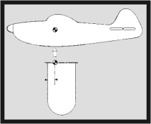
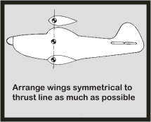
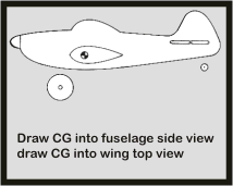
I know this all sounds mighty complicated. It’s somewhat difficult to explain it with words, so I have included a few sketches. These should make things easily understandable.
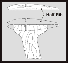
Also I think that the vertical location of the leadouts has not been designed carefully enough on many biplanes (including mine). What is not a problem with a monoplane can be quite tricky with a bipe. Since it's difficult to guess the vertical location of the CG before the airplane is finished , a line guide with provisions for horizontal and vertical adjustment is a big help. We can expect the CG location to be slightly - say about half-an-inch - below the engine thrust line (with an inverted mounted engine) but, of course, this depends on design. The line guide is then mounted on the strut in the same vertical place as the CG. With the line guide adjustable this shouldn’t be a problem. Horizontally we use the conventional amount of three degrees backward rake as a starting point. One additional idea about struts: if we spend a few thoughts about their shape and installation and carefully plan ahead, they can serve as a welcome structure to help precise aligning of the wings, and to keep control about wing incidence ( see sketch ). Those simple “N” struts (as on the Tiger Moth or similar old timers) look nice, but they are not easy to install and are heavy if built from wire. Plywood struts are simpler and lighter. Remember that fancy plywood strut shapes expose large areas to the air ( vortices ) which may result in unpleasant, uncontrollable motion when flying in wind. On the other hand carefully designed sheet struts might actually help line tension. So take your choice. No choice should be taken when it comes to rigging wires. Even if you make only modest aerobatic demands - forget the wires! We already have lots of drag, and our airplane will look very pretty even without them.
Many
flyers have experienced more than acceptable “wobbling” in
corners. It’s especially true for those airplanes which were intended
to resemble a lovely “Pitts” or any similar beauty. But also
some more functional designs can suffer more or less from the infamous
“bipe wobble”. That’s no surprise. The more compact
layout of the biplane as mentioned above ( smaller span, line guide position
) is very often combined with a shorter fuselage shape. This results in
less tailplane moment arm, less fin moment arm, and less rear fuselage
side area. All this will reduce stability around the pitch axis and yaw
axis. This is why I prefer to keep conventional proportions. We also have
to consider an additional aspect. Since we decide our engine size depending
on wing area and weight, we now have a lot of power for our reduced wing
SPAN. And with the same propeller ( as on the monoplane ) the forces created
by the propeller are much more effective now. I don’t know enough
about P-factor effecting our airplanes ( Al and Ted should be the experts
who can answer these questions ). However from early experience I’m
absolutely convinced that Gyroscopic Precession can induce strong yaw
moments and plays a big role ( roll ?) in affecting the performance of
our small ( span ) toys. Again a good reason for high AR wings and not
too short a fuselage.
If you think about it, shape and looks have always been a big argument
in favour of biplanes. Sentimental feelings and nostalgic viewpoints seem
to have more influence than rational considerations and science. But I
think this is not such a bad situation. Advanced technology is almost
wasted time and effort on a biplane anyway, as long as we’re looking
for top stunt performance. If we want to win the National Championships
we’d better build a conventional stunter with better flying characteristics.
The challenge to make a biplane fly lies on another level. It's like control
line flying in general. Its obvious limitations are not a hindrance to
our creativity. It yields a challenge in itself. I know that a monoplane
airplane can fly better. But - how well can I make a biplane fly ?! Success
is not only measured in the numbers of trophies and contest placings.
It is also the successful flight of our new biplane creation which flies
“almost as good” as the Nobler ( fill in your favorite here
).
From my careful formulations you will have noticed that this is not a scientifically approved 100% save biplane guide. Rather it's a summary of my experiences mixed up with some strongly believed aerodynamic laws which I cannot simply change according to my desire. Good luck with your next biplane design.

P.S. You never stop learning. A recent discussion about bipe matters in the Stuka Stunt forum a Mr. Serge Krauss detected a mistake in my thoughts about biplane design. I want to make it quite clear that I'm not an expert in Aerodynamics. What I write is to the best of my knowledge. So if ever I'm in error I honestly accept corrections; actually I invite you to tell me so. I always want to learn and I don't want to give wrong information. Mr. Krauss comments about the efficiency of biplanes:
"Biplanes are not at a disadvantage regarding tip vortices. In fact their ideal-case induced-drag efficiency with infinite wing separation is 200% that of the "equivalent" elliptical monoplane wing (same area and span). When wings are stacked close enough to be practical, that advantage reduces to 136%".