 1 BUILDING the 2010 THUNDERBIRD Chapter 1. The wing |
 2 MAY 2010 Last month I crashed the 2007 Thunderbird so I decide to build another. The old one had a problem that always bothered me: the wing tips were crooked. |
 3 MAY 2010 The problem was caused by the hideously complicated (albeit beautiful) elliptical shape of the wing, plus some dope shrinkage. |
 4 May 2010 The only solution is to build a new one. I thought about using the old wing but it was already overweight because of a previous repair. |
 5 MAY 20010 I buy a set of 1959-Thunderbird laser-cut ribs from Eric Rule in the USA - good bloke Eric. The wing jig ensures perfect alignment. |
 6 MAY 2010 I intend using 3 mm diameter "pivot point" hinges on this plane. The hinge is simpler but fitting them requires a high level of accuracy so I make a jig to drill the holes in the wing T.E. |
 7 MAY 2010 For the wingtips, I make a sandwich of two layers of 6mm balsa with ½ mm ply in the middle epoxied together. I left it to cure overnight under quite a bit of weight. |
 8 MAY 2010 The next morning I draw the shapes and cut them with the jig saw. |
 9 May 2010 On the previous model I'd had terrible trouble getting the TE curvature aligned properly. This time I used the trusty laser. |
 10 MAY 2010 Herein lies the problem with the T'Bird wing design. As the wing thickness curves towards the tip, and the inside of this part is a different width to the outside, the top and bottom surfaces are compound curves. Very beautiful but difficult to build accurately. |
 11 MAY 2010 I sand it to shape and refit it using the laser. The .5mm ply provides a good reference for the laser beam to follow. See how it plays tricks with your eyes? The tip appears to curve upwards but the laser says otherwise. |
 12 MAY 2010 I make a bellcrank with tiny ball bearings top and bottom. There is absolutely no play in any direction. The main load is still taken by a brass sleeve; all the bearings do is remove any slop in the assembly. |
 13 MAY 2010 This time I'm using bronze bushed aluminium ball joints. The thin aluminum sleeve on the carbon fibre rod prevents it from splitting. Note: after flying the plane for a while, the metal ball joint fell apart. Replacing it with a nylon one was a BIG job. |
 14 MAY 2010 I reverse the bellcrank to make the front line up. I do this to counter the gyroscopic precession experienced with tight outside corners. The propeller is a gyro and, when it ts rotated around the pitch axis with up or down elevator, there is a force at 90° to the turn, i.e. yaws inwards and outwards. This is why the rotary engine in WWI biplanes was a failure. |
 15 MAY 2010 I tip the wing upside down ready to do the bottom sheeting. |
 16 MAY 2010 The LE sheeting and rib caps have been fitted to the underside of the wing. To prepare for the fitting of the wing tip, I use the laser to align the wing along its roll axis. |
 17 MAY 2010 I then come around to the wing tip and align the wing on its pitch axis. |
 18 MAY 2010 And then fit the wing tip. I do the easy tip first; the one without the leadouts. Notice the compound curve of the wing sheeting as it curves toward the tip. I also discovered to my horror that the outboard rib caps need to twist from L.E. to T.E. (from the 11th to the 13 rib). The twist has to be built into the rib caps so that the tissue lies flat across them. |
 19 MAY 20010 Outboard wingtip complete and the weight box is in. I put some extra bracing in at the tip in the hope that it might help to reduce dope shrinkage. Are you wondering how I intend to withdraw the steel rods? |
 20 MAY 2010 It's time to stop and fill in a few dings and to cover up some mistakes. Some years ago John Elias introduced me to West System epoxy. It's very thin and, when mixed with microballoons, makes an excellent easy to sand filler. Great for fillets too. |
 21 MAY 2010 The inboard tip is ready to go on. Same as before, align the wing on the roll axis . . . |
 22 MAY 2010 . . . and then align the wing on its pitch axis. A few drops of cyano secures the tip in place. Why didn't I make the the tip and the T.E. as one part? Because I never thought of it. Were I ever to build an elliptical wing again, I'd make the tip and the T.E. right up to the flap from one 3-ply piece. |
 23 MAY 2010 Wing tip complete. The "X" bracing between the last two ribs adds surprising rigidity to the tip. |
 24 MAY 2010 I'm starting to make the flaps. I find a lovely piece of ¼ grain with which to make them. Before sanding in the airfoil section, I drill the hinge holes accurately. |
 25 MAY 2010 A tip we got from Ian Smith some years ago was to reinforce the part of the flap that the control horn goes through. This makes it easier to twist the flaps should you need to. This reinforcement is six ply made by gluing two pieces of lite 3-ply together. |
 26 MAY 2010 I fill in the old holes with balsa and cut a slot in the T.E. for conventional hinges. See how large the hole is now? It started off as a 1/8" hole but grew into one much larger. |
 27 MAY 2010 I discover that there's some real problems with this kind of hinge: 1) It's shaped like a rasp and very quickly enlarges the holes into which they are supposed to fit; 2) the diameter is too large for the thin flaps of the Thunderbird, 3) the joint is way too stiff and does not move easily and 4) the hinge is too long and protrudes through the surface of the flap. |
 28 MAY 2010 The new flaps are fitted and they drop under their own weight as they are supposed to. |
 29 MAY 2010 The next step is to seal the flaps and wing with epoxy. Reason: It will probably be a couple of months before fitting the wing to the fuselage and if I leave it hanging around for that length of time, warps are almost certain. |
 30 MAY 2010 The epoxy I use is a slow cure laminating resin, thinned 50/50 and then applied to all surfaces with a brush. It goes on like water and I wipe off the excess with paper towel. I've learned that it will probably take 3-4 days before it is hard enough to sand. |
 31 BUILDING the 2010 THUNDERBIRD Chapter 2. The fuselage |
 32 MAY 2010 I'm now starting to build the fuselage. The first thing in building the fuselage is to build the motor mounts. I build in 1° of out thrust. It also helps later on in the construction to recess the blind nuts a little. |
 33 MAY 2010 The 1° offset is quite noticeable. |
 34 MAY 2010 I also build in 1½° of down thrust. This is the ST46 Plasma out of the crashed Thunderbird. I'll be using it again. |
 35 NOVEMBER 2012 There's a good reason for building in these offsets and this paper explains why |
 36 NOVEMBER 2012 asymmetric propeller loading is the main reason for building in the engine offsets. |
 37 NOVEMBER 2012 When it comes time to fit the wing to the fuselage, I will be use my laser to ensure that the 1½° down thrust relative to the wing chord is maintained. |
 38 NOVEMBER 2012 You are free to disagree (between yourselves) |
 39 NOVEMBER 2012 The discussion paper in PDF format. |
 40 MAY 2010 The two bearers are exactly parallel. This is important when it comes to building a symmetrical fuselage , which it needs to be if the 1° offset is to mean anything. A banana-shaped fuselage would produce an offset of >1° or <1° but not =1°. |
 41 MAY 2010 I always fill the nose with balsa and then grind away the engine bearers to create a continuous flowing curve towards the spinner. |
 42 MAY 2010 Fuselage sides cut out. |
 43 MAY 2010 Fuselage doublers cut out. The grain is vertical. |
 44 MAY 2010 Fuselage doublers glued to motor mount. |
 45 MAY 2010 Doubler with epoxy in the centre. Dry outside edge is for cyano to glue the fuselage side to the doubler. |
 46 MAY 2010 Fuselage sides glued on. |
 47 MAY 2010 Centred in the fuselage jig. To add the fuselage formers, I work from the front to the back to make sure the fuselage is symmetrical. |
 48 MAY 2010 First fuselage former centred and glued in place. |
 49 MAY 2010 Fuselage is symmetrical. |
 50 MAY 2010 Fuselage in the jig. Tip the fuselage upside down in the jig and it still fits thus assuring that the fuselage is not banana-shaped. About now I discover that the cowl line is wrong and that I'll need to add ½". I thought it didn't look right. |
 51 MAY 2010 I always add crossbracing at the top and bottom of the fuselage. I drop the wing in from the top so I finish the bottom completely. Putting the crossbracing in now helps to maintain fuselage alignment. |
 52 AUGUST 2010 Landing gear is a Bolly carbon fibre unit which is unfortunately no longer available. I sand some off the trailing edge and reshape the cross-section from flat to airfoil and save 4 grams. The wheels are from Brodak and are lighter than they look at 20 grams the pair. The complete assembly weighs only 56 grams (2 ounces) |
 53 JUNE 2010 Bottom sheeting is on. Cowl line is reinforced with .4mm ply. I hollow out the 6mm balsa bottom sheeting and save a mere 2 grams - not worth the effort. |
 54 JUNE 2010 It's very important that this bit is square otherwise the vertical fin could be out of alignment. I take inordinate care to get the alignment right. |
 55 JUNE 2010 Cowl parts spot glued to the fuselage. |
 56 AUGUST 2010 BACK FROM HOLIDAY. The cowl is nearly finished but now needs to be covered in fibreglass cloth (.6 oz) |
 57 AUGUST 2010 I'm ready to start shaping the top block. It's stuck on with many spots of thick cyano so that it can be popped off later. The blue tape protects the fuselage and creates a top block that is slightly wider than the fuselage. This helps later on. |
 58 AUGUST 2010 Time to start building the balsa canopy. This is a 1½" block of ultra light basla - about 4½ lbs. |
 59 AUGUST 2010 Shaped square and ready to sand to shape. |
 60 AUGUST 2010 Sanded to shape. |
 61 AUGUST 2010 Hollowing out reduced the weight to 5 grams. A plastic cockpit weighs around 20 grams. |
 62 AUGUST 2010 Shaping of the top block is complete and I can now pop it off and hollow it out. |
 63 AUGUST 2010 With the cockpit and the fin/rudder complete, I mark their outlines on the top block and start shaping it. |
 64 AUGUST 2010 Top block hollowed out and weighing only 30 grams. Countries have gone to war to get balsa this light. |
 65 AUGUST 2010 The tailwheel assembly: weight 4 grams. The cable is for the self launcher. The bit sticking up belongs to the cable and is reinforced with silver solder. The weight of the plane when using the self launcher is therefore taken entirely by the cable and not the tailwheel. |
 66 AUGUST 2010 Fuel tank and plumbing is finished. I'll be running muffler pressure - the ST46 seems to like it. It reduces the difference between launch revs and flight revs. |
 67 AUGUST 2010 Muffler pressure feeds in through the uniflow vent. The tank is a metal clunk tank. There's an aluminium sleeve in the fuselage side to support the brass tubing, necessary because this connection is continually removed and refitted during refuelling. |
 68 AUGUST 2010 Mount for the tailwheel assembly. I like to have a removeable landing gear and tailwheel to make painting the model easier. |
 69 AUGUST 2010 Pad for the landing gear. The Landing gear is held on with four 2-56 screws and can be moved forward or back for flying on pavement or grass (rearward for pavement). This reduces bounce on landing. THIS IS THE END OF THIS TOPIC. |
 70 BUILDING the 2010 THUNDERBIRD Chapter 3. The tailplane (or horizontal stabiliser) |
 71 AUGUST 2010 I start working on the tailplane and elevators. Note that the hinges are fitted already. I make a template so that both tips will be the same shape. |
 72 AUGUST 2010 A handy tip is to drill the holes for the elevator horn before the elevators are shaped. This ensures that the holes are central. |
 73 AUGUST 2010 The box section is complete and ready for shaping. I always fit the ribs last because it's too easy to sand a dip into them at this stage. All leading and trailing edges are 3 ply (½ mm ply sandwiched between two strips of balsa). |
 74 AUGUST 2010 Tailplane and elevators are sanded to shape. Now I can fit the ribs. |
 75 AUGUST 2010 This is the control horn that I made for the elevators. |
 76 AUGUST 2010 The tailplane and elevators are finished and sealed with epoxy thinned 50/50. |
 77 AUGUST 2010 Each rib has a tiny hole drilled in it so that air trapped under the covering can equalise with the outside pressure. Another tiny hole bleeds the air to the outside world. This stops the covering from ballooning out on hot days. I'll cover and dope this assembly shortly so that it doesn't warp while waiting to be installed. |
 78 AUGUST 2010 Starting the tissuing process. I always use heavyweight tissue because of its durability. I first spray the tissue with water, lay it on and then dope it down with thinned nonshrink dope. |
 79 AUGUST 2010 I use nonshrink nitrate dope from the first coat because all dope shrinks. The Rand-o-proof dope is for full sized aircraft and unfortunately is tinted green. However, the quality is superb as you would expect. The dope is thinned 50/50 with lacquer thinner and applied with a wide brush. |
 80 AUGUST 2010 The tail assembly has three thinned coats applied at this stage. I'll put another couple of thinned coats on before I start applying thinned dope/talc. It is important not to sand between coats until there is a reasonable coating - otherwise sanding through the tissue is probable. It's also very important to use dope/talc as the filler coats because each coat dissolves into the coats below. This helps to prevent the base colour from lifting when applying the final trim colours. > THIS IS THE END OF THIS TOPIC. |
 81 BUILDING the 2010 THUNDERBIRD Chapter 4. The fin/rudder |
 82 AUGUST 2010 I glue some hard balsa square to the rest of the edges to help prevent the assembly from warping. A straight and square fin/rudder is very important and when installed, it must be exactly 90° relative to the hinge lines. |
 83 AUGUST 2010 The fin/rudder is finished and sealed with epoxy thinned 50/50. |
 84 BUILDING the 2010 THUNDERBIRD Chapter 5. Assembly |
 85 AUGUST 2010 Assembly begins. I screw two 2-56 screws into the landing gear. These are adjusted to adjust the fuselage on the roll axis. |
 86 AUGUST 2010 Same again in the tailwheel to adjust the pitch axis. |
 87 AUGUST 2010 I adjust the left and right screws in the landing gear support to level the fuselage on the roll axis. |
 88 AUGUST 2010 First trial fit of the wing in the fuselage. The inboard wing is too high. |
 89 AUGUST 2010 Tim Gee told me many years ago that if there is a difference between your measuring instruments and your eyes, then trust your eyes. It's obvious without the laser that the inboard is high. |
 90 AUGUST 2010 Before adjusting anything, I come around to the side and can see that the T.E. is also too high. |
 91 AUGUST 2010 After some sanding, the horizontal alignment is pretty good. |
 92 AUGUST 2010 A little trick that I learned only last year is to sand away most of the wing opening so that the wing is supported by four points - two at the front and two at the back. This makes alignment of the wing in the fuselage fairly easy. Once the wing is glued in place, the gap can be taken up with balsa shims. |
 93 AUGUST 2010 You can see the gap between the fuselage and the wing but it's making firm contact at the T.E. This gap is filled in with balsa shims after the wing is glued in place. |
 94 AUGUST 2010 Checking that the wing incidence is zero° |
 95 AUGUST 2010 I also check the incidence with my trusty old Incidence Meter. |
 96 AUGUST 2010 The final step is to align the T.E. of the wing with the fuselage. As the fuselage is symmetrical, I set the angle the same on both sides. NOTE 2016: At this step, I now use the laser up the centre of the wing. |
 97 AUGUST 2010 The wing is glued in at the four contact points with a mixture of West Systems epoxy and microballoons. The laser provides a final check that the wing is being glued into the right position |
 98 AUGUST 2010 About now, I discover that I've forgotten to put the flap control horn in. Never mind, it's a simple fix. |
 99 AUGUST 2010 The flap horn installs fairly easily. I then make a template for the wing cutout. |
 100 AUGUST 2010 Because of the template, the wing cutout fits very well. I've put the fillets in already using a wet mixture of West System epoxy and microballoons smoothed with metho. This is the result before sanding the fillets. |
 101 AUGUST 2010 I'm starting to fit the controls. The insert for the C/F pushrod is made from titanium. Note the plywood reinforcement behind the wing which is required because this section of the fuselage twists a lot during flight. NOTE: Titanium is not vibration resistant; it broke. Some time later, the metal ball joint fell apart. Both were mega major repairs. |
 102 AUGUST 2010 I use a 3 mm titanium turnbuckle to help adjust the flap/elevator relationship. The 3 mm quicklink is no longer a quicklink because it now has a 3/16" stud soldered into it. The elevator horn is brass bushed. Note: The titanium turnbuckle broke, luckily discovered on the ground, so I did not crash the plane. It was still a major repair though. |
 103 AUGUST 2010 Aligning the flaps. The left flap is too low. |
 104 AUGUST 2010 It's quite a bit too low. |
 105 AUGUST 2010 After some careful bending of the flap horns (with the flaps removed), the flaps are aligned. |
 106 AUGUST 2010 Now the length of the pushrod can be adjusted to get the flaps and elevators neutral. |
 107 AUGUST 2010 Now it's time to glue the tailplane into position. I first start by aligning the wing horizontally. |
 108 AUGUST 2010 The elevator hinge line is set parallel to the wing hinge line looking from both above and from behind. The tailplane is glued in four spots using epoxy and microballoons and is held in position using pins only - no weights. |
 109 AUGUST 2010 The horizontal alignment is still OK. |
 110 AUGUST 2010 As is the fore and aft alignment. |
 111 AUGUST 2010 Checking that fore and aft distances are equal. |
 112 SEPTEMBER 2010 Top block is glued on using a wet mixture of West Systems epoxy and microballoons. This makes the fit appear to be better than it really is. |
 113 SEPTEMBER 2010 I always leave a small gap above the tailplane when I glue the top block on. This helps to stop the top block from pushing the tailplane out of alignment when the top block is taped and glued onto the fuselage. |
 114 SEPTEMBER 2010 Time to fibreglass the front end. I use Z- Poxy finishing resin thinned 1/3 (1:1:1) and painted on with a disposable brush. Rubber gloves are very handy; damn but this is a messy job. The paper towel mops away the excess. |
 115 SEPTEMBER 2010 Fibreglassing of cockpit and front end is complete. |
 116 SEPTEMBER 2010 Dennis Percival made this handy tool for me a couple of decades ago. It's a great way of getting the spinner to fit neatly with the front end. |
 117 SEPTEMBER 2010 I knocked my laser over and broke it so I struggle on without it. I'm aligning the tailplane to make it square with the workbench. |
 118 SEPTEMBER 2010 I slide the tapered bit of balsa under the wing until the hinge line is level. |
 119 SEPTEMBER 2010 Then the fin/rudder is glued on using the square for alignment. Once again, the gluing is done using a wet mixture of West Systems epoxy and microballoons. |
 120 SEPTEMBER 2010 Assembly is complete. Fillets are on the tailplane, rudder and cockpit. Now I can start the bit I really enjoy: putting the colours on. THIS IS THE END OF THIS TOPIC. |
 121 BUILDING the 2010 THUNDERBIRD Chapter 6: Finishing |
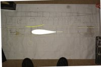 122 SEPTEMBER 2010 I need an accurate representation of the fuselage so that I can start drawing the graphics so I take a photograph of the plan, import it into Corel Draw and sketch around the picture to get the outline. That's my feet in the picture. |
 123 SEPTEMBER 2010 Then I delete the photograph and I'm left with the outline. |
 124 SEPTEMBER 2010 Version 1. Not bad I thought. |
 125 SEPTEMBER 2010 Version many tries later. I played around with the colour scheme a bit more and added the Thunderbird graphic. I decide to send it to Claus Maikis for comment. |
 126 SEPTEMBER 2010 Claus likes the design but thinks the colours are awful. He also suggested a change of font and to overlay the lettering onto the striping. I google "Old German fonts" to find to find the "Fraktur" font and download it from the internet. |
 127 SEPTEMBER I start to apply the finish. At this stage, the whole airframe has a coat of thinned laminating epoxy applied and all sections that require fibreglassing are done. |
 128 SEPTEMBER 2010 Weight at this stage is 1090 grams (38½ ounces). Without trying too hard the finished weight should be around 1275 grams (45 ounces) which is quite OK for a 610 sq in wing. I'm really pleased with the way the 1¾" Brodak spinner flows into the fuselage and cowl. |
 129 font color="yellow" size= "1">SEPTEMBER 2010 I want a grain filler. I find that if I mix laminating epoxy, thinned 200% (1:1:4) and mix it with talcum powder, I get a really nice matt coating that sands reasonably easily. |
 130 SEPTEMBER 2010 I got the talc off the internet. It has no additional chemicals added and is perfect for our needs. |
 131 SEPTEMBER 2010 When the epoxy has hardened, the flat surfaces are then "blocked" which means using a block to sand the areas flat. The curved areas are sanded using sand paper doubled over and glued. I used 220 grit for this. |
 132 SEPTEMBER 2010 The result after sanding is a beautiful, completely filled balsa grain ready for the next finishing steps. I also fill and sand the balsa on the wing L.E. and T.E. in a similar manner. |
 133 SEPTEMBER 2010 From here on, I use my standard finishing technique. I use non-shrink dope thinned at least 100% (1:1) that is applied with a high quality artist's brush. High quality thinners prevents the dope from going milky when it is applied. If the dope is not thinned enough, it will leave brush marks. If it is too thin, it will leave cracks similar to a dry creek bed in the outback. |
 134 SEPTEMBER 2010 I apply the tissue wet and dope the edges. |
 135 SEPTEMBER 2010 The first thinned coat is applied sparingly all over including the balsa. I'll give it four or five more thinned coats before I use the dope/talc mix. |
 136 SEPTEMBER 2010 Five days have passed and each day I applied one coat of thinned dope on the tissue. I was told many years ago that each coat of dope needs 24 hours to harden before applying the next coat and I always do this. |
 137 SEPTEMBER 2010 After nine coats on the stab, there are still no brush marks. |
 138 SEPTEMBER 2010 Six days have passed and that means I've applied six coats of thinned dope/talc. The tissue is still almost free of brush marks. |
 139 SEPTEMBER 2010 On day seven, I wet-sand the tissue with wet/dry 800 paper. Because there were light brush marks only, it requires very little sanding. I wet-sand the balsa with 600. By wet I mean bare minimum of water, just enough to float the particles away and then immediately wiped clean with a paper towel. |
 140 SEPTEMBER 2010 I clean the whole airframe with prepsol, let it bleed off overnight and then mist on undercoat from a spray can. I think next time I'll use a 2K white undercoat instead. This undercoat was a little "gummy". NOTE: 2K white undercoat only comes in 4 litre cans, so I do not buy it. |
 141 SEPTEMBER 2010 It looks very smooth. Tomorrow I'll wet-sand it with 800 all over again. For the tissue, I sand it with the wet/dry paper doubled over, glued together and cut to a 1 cm square - just enough to cover the tip of my finger. |
 142 OCTOBER 2010 Many days later, I've sanded the plane all over and removed most of the undercoat. For the first time in a long time, I do not sand through the tissue. Reason: I start with 800 (wet) and finish with 1200 (wet). |
 143 OCTOBER 2010 I don't sand through the tissue, I punch a hole in it instead. |
 144 OCTOBER 2010 Meanwhile, Dennis Percival decides that the old Thunderbird can be repaired. After repair, he gives it back to me to repaint. I never believed that the totally trashed aeroplane could be resurrected. It goes to a good home. |
 145 OCTOBER 2010 The basecoat of white lacquer is on. |
 146 OCTOBER 2010 I'm using automotive lacquer base coat and trim colours which means it needs a coat of 2K clear to protect the finish and to lift the colours. |
 147 OCTOBER 2010 I've done the canopy and I'm starting to mask the paint scheme. |
 148 OCTOBER 2010 The canopy will need a clear coat to get the full depth of colour. |
 149 OCTOBER 2010 The wing stencils: positive italics for the left wing and negative italics for the right wing. The italics are done using the "perspective" command in Corel Draw. |
 150 OCTOBER 2010 Graphics on the left wing are complete. Next step is to mask it off before the fine line masking tape moves. At this stage, the fuselage is fully masked and ready for paint. |
 151 OCTOBER 2010 The Thunderbird logo works out pretty well. I remove the pencil lines with T Cut before the clear goes on. |
 152 OCTOBER 2010 Fin decoration is on. Where the fine line masking tapes cross each other, I soften the intersection for about ½ second with a heat gun and push the tape down with a paddle pop stick shaped like a blunt chisel. |
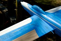 153 OCTOBER 2010 It's now ready for the first of three trim colours. I mask it so that the last colour to be sprayed is the last colour to be unmasked. That's quite a bit of extra work now but it pays off later. |
 154 OCTOBER 2010 The first colour is on at long last. The weather has not cooperated at all. |
 155 OCTOBER 2010 This is the lightest of three metallic mauve/purples to go on. The next colour is the intermediate shade. |
 156 OCTOBER 2010 The first colour is masked off and the area for the second colour is exposed. |
 157 OCTOBER 2010 The second colour is on and is an intermediate shade of metallic purple. One more colour to go, then a few ink lines followed by the 2K clear. |
 158 OCTOBER 2010 Final colour of three is on. To me, taking the masking tape off to reveal what you have created is the most exciting part of the whole building experience. Tony Bonello didn't like the way the purple fuselage stripe "just ended". I agreed and fixed it later. |
 159 November 2010 Weight is 46½ ounces - 1320 grams - acceptable but not brilliant. The three metallic colours and the clear coat added 8 oz (230 grams). This is a little more than I expected. |
 160 November 2010 I decide against ink lines. I put some ink lines on the underside of the elevators but I don't like them - too wobbly because of my hand shaking. |
 161 November 2010 The finished project. It's had a coat of clear to finish it off. There has been no major sanding since sanding the final coat of dope/talc. |
 162 November 2010 I would use the metallic trim colours and the coat of clear again but I would spray the white basecoat with 2K instead of lacquer. The 2K is vastly more forgiving although it would need wet-sanding with 1200 for the trim colours to stick and this is a significant extra step. |
 163 November 2010 I'm very satisfied with the finished result but it's full of small errors - so, next time perfect. |
 164 November 2010 I'd like to thank Claus Maikis whose comments - witty and to the point - stopped me from making some serious artistic blunders. PS: I've flown the plane and it sits level without any hunting and goes around corners fuss free; not surprising given the anal attention given to the alignment. It needed 1½ oz of tip weight so final weight is 48 oz or 1360 grams. Return to the home page |